
This is one of the measurement device that has been on my list for a while, it’s HP/Agilent 8903B distortion meter (well, Tektronix AA501 is also on my list). It’s a solid unit with combination of low distortion oscillator and analyzer (which lacked on HP 8903E model). The B version has more feature than the A version, but both offer similar combination of oscillator and analyzer.

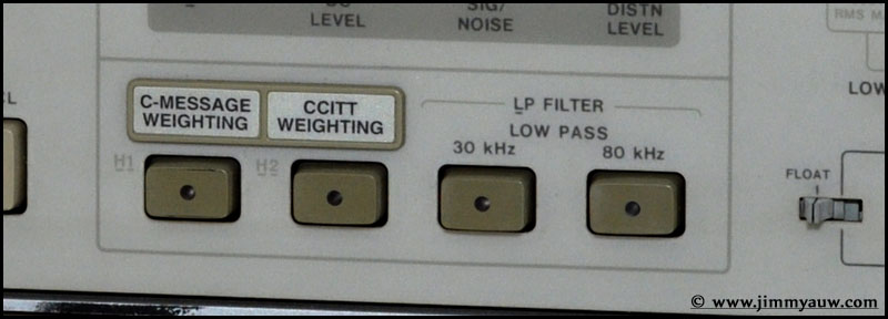
Mine comes with additional C-Message Weighting Filter (Option 013) and CCITT Weighting Filter (Option 051). I don’t think I will have a lot of usage for both filter – gosh, I do prefer it comes with 400 Hz high pass filter or ‘A’ Weighting).
HP 8903B equipped with standard 30 kHz and 80 kHz low pass filter. A bit different with HP 8903A version.
Options installed are written on the top of the unit. Option 909 is Rack Flange and Front Handle Combination Kit. Not related with filters or internal function.

The card “cheat sheet” can be pulled from the front-bottom side. A quick way to operate or find out the meanings of the error code. Well, it’s an 30 years old device. Don’t expect easy to read error message shown on the high resolution color LCD Panel. We are talking with 7 segments display only here.
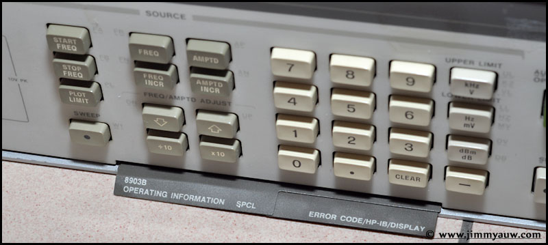
The “cheat sheet”. Click to zoom into a larger view.

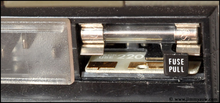
Another interesting part is the fuse holder and voltage selector. You don’t expect an universal switching voltage input 30 years ago, right? Off course not. Therefore, we have to switch the input voltage manually. Using a switch? Nooo…. HP decided to use an unique small PCB which needs to be inserted correctly to select the correct input voltage.
Pull the trigger to the front-left side to force the fuse out from the holder.

Now you can see small PCB below the fuse holder. The idea is you need to pull it out (which turns to be quite hard to be done).

With a small modified paper clip, I use the hole on the PCB to pull the PCB slowly out. Be gentle, you don’t want to break the PCB which I don’t think you can find any spare around!

Here is the PCB. It’s dual side and as you can see below, there are several combinations which turns into different input voltage option.

Now I plug back and set to 220 VAC input. As you can see below, the 220 marking is obvious seen from the front side (after the fuse installed back to the holder). It means that this device is already configured to work on 220 VAC input voltage.
Another shoot from the back side. An GPIB port (the GPIB-USB connector is quite expensive). Also there are several connectors to connect this device to a plotter to print the sweep result.

That’s all for now. Let’s find some time to open the unit, check, clean, then power it up and calibrate.


Ayung
June 12, 2014 09:11Gak ada yg comment, ane yg isi aja ahhh mumpung pertamax
Auw Jimmy
June 12, 2014 10:01Abis Abut, jadi Ayung? Besok jadi siapa lagi Boss?
Thanks.